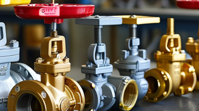
What Is a Ball Valve Control Valve?
A Ball Valve Control Valve combines a rotating ball mechanism with an actuator and control system. It regulates fluid flow by turning a drilled ball inside a sealed body. When the bore aligns with the pipeline, fluid passes through. A quarter-turn movement can quickly reduce or stop the flow.
This design is common in water treatment, process plants, heating systems, and industrial pipelines. Its compact shape supports reliable shutoff, while a suitable actuator enables automatic operation. Engineers may choose pneumatic, electric, or hydraulic actuation, depending on speed, available utilities, and control requirements. A properly selected valve should match the medium, pressure, temperature, pipe size, and expected flow range.
The details matter.
From field experience, a ball valve can perform smoothly for years when its seals, materials, and actuator are correctly specified. However, not every ball valve provides precise throttling. Standard full-port models may respond sharply near closed positions, making accurate control more difficult. Specialized control-ball designs can improve flow regulation, but they may cost more and require careful sizing.
Reliable selection also requires checking manufacturer data, installation conditions, maintenance access, and applicable industry standards. Incorrect sizing can create noise, vibration, unstable flow, or premature wear. Even a high-quality valve cannot compensate for poor system design. This guide explains the operating principle, major types, benefits, limitations, and practical selection considerations of a Ball Valve Control Valve. Some applications still demand deeper analysis. That is where engineering judgment remains essential.
Ball Valve Control Valves: Definition, Function, and Industrial Role
What Is a Ball Valve Control Valve?
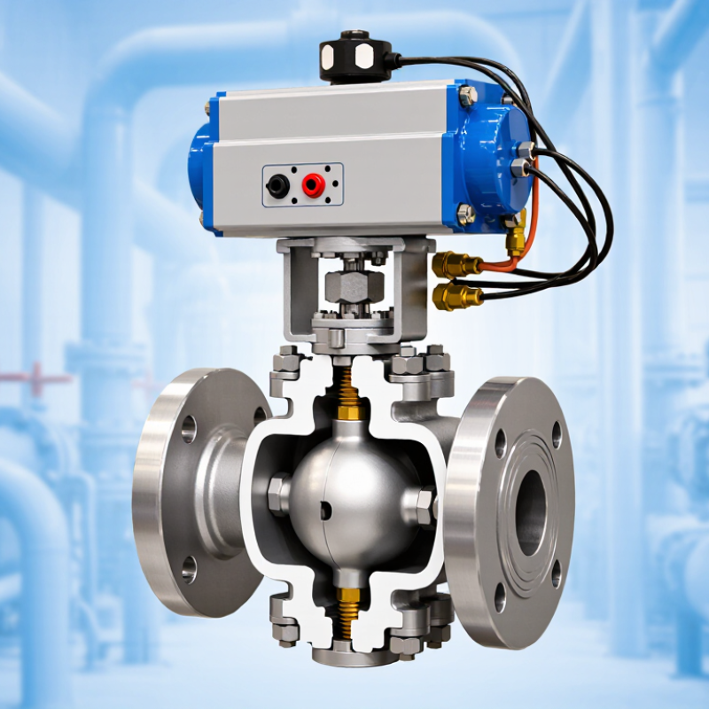
A ball valve control valve regulates fluid flow through a rotating ball with a precisely shaped opening. An actuator turns the stem according to a control signal. As the ball rotates, the opening changes, adjusting flow rate, pressure, or temperature in a process line.
Unlike a simple on-off ball valve, a control version is designed for repeatable throttling. It may include position feedback, a digital controller, and a fail-safe actuator. In industrial service, technicians use these valves for water treatment, chemical processing, compressed air, and fuel systems. The compact body creates a short flow path and often reduces pressure loss. The geometry matters. During commissioning, engineers check travel response, leakage, vibration, and actuator performance under actual operating conditions.
Selection requires more than matching pipe size. Engineers review flow coefficient, pressure rating, fluid temperature, viscosity, corrosion risk, and required shutoff class. A poorly sized valve can hunt, erode, or operate near its seat continuously. That mistake is common. Ball valves can provide strong isolation, but not every design performs well during severe throttling. Cavitation and flashing may also damage internal surfaces. Field experience shows that clean installation, correct calibration, and regular inspection strongly affect reliability. Still, operating data can challenge the original design assumptions, so control performance deserves periodic review.
Key Components: Ball, Stem, Seat, Actuator, and Positioner
What Is a Ball Valve Control Valve?
A ball valve control valve regulates fluid flow by rotating a drilled ball inside its body. The ball controls the passage area, rather than simply opening or closing it. Its stem transfers torque from the actuator to the ball. A properly aligned stem reduces friction and supports stable movement. Small installation errors can still create uneven wear.
The seat surrounds the ball and forms the sealing boundary. It must match the fluid, pressure, temperature, and required leakage class. Soft seats can provide tight shutoff, while metal seats tolerate harsher service. Neither option is perfect. Debris, excessive speed, or poor material selection may damage the sealing surface. I have found that clean piping often matters as much as valve design.
The actuator supplies the force needed to rotate the stem. Pneumatic actuators are common where fast response matters, while electric units support controlled positioning and easier system integration. The positioner receives a control signal and compares it with actual stem movement. It then adjusts actuator pressure or power to correct the error. Calibration should include zero, span, travel direction, and fail position. A valve may appear functional but still control poorly when its positioner is misconfigured. Check the feedback linkage carefully. Small backlash can cause noticeable flow variation, especially near low openings.
What Is a Ball Valve Control Valve?
Key components: Ball, Stem, Seat, Actuator, and Positioner
Chart explanation: The chart illustrates a commonly used 4–20 mA positioner command. In this simplified linear example, 4 mA represents 0% commanded opening and 20 mA represents 100% commanded opening. The actual flow characteristic can vary depending on the valve design, trim, and control configuration.
Ball: The rotating closure element that regulates flow. Most ball valves use approximately a 90-degree quarter-turn.
Stem: Transfers rotational movement between the actuator and the ball.
Seat: Provides the sealing surface around the ball when the valve is closed.
Actuator: Converts pneumatic, electric, or hydraulic energy into stem movement.
Positioner: Compares the control signal with valve position and adjusts the actuator to reach the requested position.
Control Performance: Cv Sizing, Rangeability, and 90° Rotation
What Is a Ball Valve Control Valve?
A ball valve control valve regulates fluid flow by rotating a drilled ball inside its body. Unlike a simple isolation valve, it must respond accurately to changing control signals. Its 90° rotation gives fast movement from closed to open. That speed can be useful, but it may also create overshoot in sensitive systems.
Cv sizing determines how much flow passes through the valve at a specific pressure drop. Engineers should calculate Cv near the normal operating point, not only at maximum capacity. A valve that is too large may operate nearly closed, making small actuator movements cause large flow changes. A valve that is too small can restrict the process and waste pumping energy. Field data, fluid density, viscosity, temperature, and pressure recovery all affect the calculation.
Rangeability describes the usable relationship between maximum and minimum controllable flow. It is not merely a catalogue number. Actual rangeability depends on trim design, actuator resolution, installation, and process conditions.
In commissioning work, a valve may perform well on paper but react poorly after piping changes. That deserves investigation. Small details matter.
The 90° travel should match the valve’s inherent flow characteristic, such as equal-percentage or linear behavior. Equal-percentage trim often suits variable-pressure systems because each rotation produces a proportional flow change. However, this assumption can fail when pressure drop changes sharply. Testing several operating points is wiser than trusting one calculated condition. Trend logs can reveal hunting, deadband, or unstable response before operators notice a serious process deviation.
Pressure Classes, Temperature Limits, and ANSI B16.34 Standards
What Is a Ball Valve Control Valve?
A ball valve control valve regulates flow by rotating a drilled ball inside the body. It suits on-off service and many throttling duties. In field inspections, the actuator, stem, seats, and body often decide reliability more than the ball itself. A tight shutoff is useful. Poor sizing can still cause noise, cavitation, or unstable control.
Pressure class is not a fixed pressure limit. ASME B16.34-2020 lists pressure-temperature ratings for Classes 150, 300, 600, 900, 1500, and 2500. For a common carbon-steel material group near 100°F, approximate ratings range from 285 psi in Class 150 to 6,170 psi in Class 2500. These values change with material, temperature, and design details. Never transfer a Class 600 value directly to a different alloy.
Temperature changes the calculation. Higher temperature usually reduces allowable pressure because body strength and seat performance decline. A fluoropolymer seat may tolerate service near 400°F, while a metal seat can suit higher temperatures. The exact limit depends on the manufacturer’s tested design and process chemistry. That assumption is tempting—and wrong.
ASME B16.34 also addresses wall thickness, pressure testing, materials, and marking. MSS SP-61 provides relevant hydrostatic and closure-test guidance. ISO 15848-1 adds fugitive-emission test classifications for valve assemblies. Engineers should compare the datasheet with these standards, then check thermal cycling, differential pressure, and actuator torque. Small details matter. Mistakes often begin with a copied rating table.