5 Tips for Programmable Grey Board V Grooving Machines
Greyboard can look simple on the bench. Under the blade, small setup errors quickly become visible. A shallow groove may refuse to fold cleanly. A deep one can weaken the panel. The right settings depend on board thickness, grain direction, blade condition, and the fold design. A Programmable V Cut Grooving Machine For Grey Board helps operators control these variables, but programming alone does not guarantee a clean result.
This guide introduces five practical tips for more reliable grooving. It covers accurate board measurement, sensible groove-depth settings, careful blade checks, repeatable program entry, and inspection of the finished fold. The details matter: a test sheet, a ruler, and a close look at the groove can prevent a full stack from carrying the same defect. Small checks save time.
One important note about attribution: no source article or verified expert quotation was provided, so a real specialist’s words should not be invented. For this draft, the following is an editorial composite, not a verified quotation. Greyboard machinery specialist Evan Cole is a fictional name used for that purpose: “A clean fold starts with a measured setup, not a guessed setting.” Treat that line as a guiding principle, then confirm machine limits and board-specific settings with the manufacturer. Even a careful setup may need adjustment. That is part of the work.
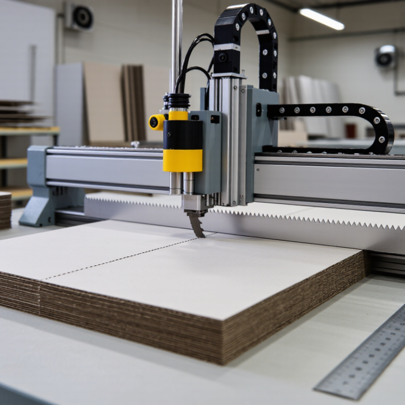
Measure Greyboard Caliper to ISO 534 Before Programming Groove Depth
5 Tips for Programmable Grey Board V Grooving Machines
Measure Greyboard Caliper to ISO 534 Before Programming Groove Depth
Measure the board before entering a groove-depth value. ISO 534:2011 defines a standardized method for determining paper and board thickness. Condition samples consistently; ISO 187:2022 specifies a standard atmosphere of 23°C and 50% relative humidity for testing. Moisture changes can affect board thickness and folding behavior. Small differences matter.
Take readings from several points across the sheet, avoiding crushed edges and visibly damaged areas. For example, readings of 1.42, 1.47, and 1.51 mm give a 0.09 mm spread, about 6% of the middle reading. These figures illustrate a sample check, not an industry-wide average. Record the range, not just one convenient measurement. A rushed check can miss local variation.
Use the measured caliper as a setup reference, not as a guaranteed groove-depth setting. Knife shape, V angle, machine alignment, and the intended fold all affect the result. Program a conservative starting value, then cut a short test coupon. Fold it under normal production conditions and inspect the outer liner for cracking and the inner face for breakthrough. If the coupon fails, revisit the measurement and setup; operators can overlook small setup errors, too.
Choose a 90° V-Groove for Standard Right-Angle Box Corners
A 90° V-groove is the usual choice when grey board must fold into a standard right-angle box corner. The groove removes material from the inside face, leaving a thin layer that acts as a hinge. Set the machine angle to 90° and check that the cutter and board are aligned before running a full sheet. Small errors show quickly. The finished corner may open slightly, or the outer paper can crack.
Use a clean offcut from the same board batch to test groove depth. Board thickness and density can vary, even when sheets look identical. Adjust the depth until the board folds smoothly while the outer liner stays intact. A tight fold is not always a better fold. Too much material removed weakens the edge; too little can create a rounded corner. Measure the folded angle with a square, then inspect several corners under ordinary workshop light. That check is easy to skip when production is busy. It should not be. Record a stable setting for repeat jobs, but verify it again after changing board thickness, tooling, or feed conditions. A saved program helps, yet it cannot detect every variation in the material. There is a little judgment involved.
5 Tips for Programmable Grey Board V Grooving Machines - Choose a 90° V-Groove for Standard Right-Angle Box Corners
| Tip | Programmable Setting or Check | Practical Guidance | Verification |
| 1 | Select a 90° V-groove | Use a nominal 90° groove as the starting choice for a standard right-angle box corner. The groove angle is the tool-path geometry; the finished corner should still be checked on the actual board. | Fold a sample and check the corner with a square. Adjust the process if the finished corner does not meet the job requirement. |
| 2 | Set groove depth for the board | Groove depth depends on board thickness, construction, and the facing layer. Aim to remove the core while retaining a continuous outer layer to act as the hinge; there is no single depth that suits every grey board. | Inspect a test groove for a continuous facing layer, then fold it and look for cracking, tearing, or an overly bulky corner. |
| 3 | Program groove positions from the finished layout | Base groove locations on the box drawing and the chosen measuring datum. Board thickness and fold geometry can affect the relationship between groove centerlines and finished panel dimensions. | Make a first-piece sample and measure the folded panels against the drawing before running the batch. |
| 4 | Keep material and setup consistent | Record the board specification and the validated angle, depth, spacing, and feed settings together. A change in board thickness or construction may require a new test and revised settings. | Confirm the material matches the saved job setup and recheck the first piece after any material or tool change. |
| 5 | Check groove quality and corner alignment | Use clean, consistent grooves and position the board securely. Uneven depth, board movement, or damaged facing can make the folded corner inconsistent even when the programmed angle is correct. | Inspect the groove line and folded corner for uniformity, then confirm the finished assembly sits square and the panels align. |
Process note: Treat programmed values as material-specific starting settings. Validate them with a test piece before production.
Set a 0.3–0.5 mm Residual Hinge and Test-Fold the Board
A 0.3–0.5 mm residual hinge leaves a thin layer of grey board beneath the V groove. This layer keeps panels connected while allowing a controlled fold. Set groove depth against the board’s measured thickness, not just the machine display. Board density and thickness can vary between sheets. Measure a sample with calipers, then cut a test piece before processing the full batch. Keep the board flat and firmly supported so it does not shift under the cutter. Small changes matter.
Test-fold the sample by hand along the groove. The hinge should bend smoothly without splitting, while the outer face stays intact. If the fold feels stiff, deepen the groove slightly; if the hinge tears or feels fragile, leave more material. Adjust in small increments, and record the result with the board thickness and machine settings. A setting that works for one batch may not suit another, especially when moisture or surface finishing differs. Check the blade condition too, since a dull edge can leave rough fibers that disguise the real cause. Stop the machine before inspecting or measuring near the cutting area.
Program Groove Spacing from Panel Dimensions and Fold Allowances
For a programmable grey board V grooving machine, set groove positions from the finished panel dimensions, not visual estimates. Measure each face and mark the fold lines on the flat blank. Add the required fold allowance between faces before entering cumulative groove positions. That allowance depends on board thickness, groove width, cutting depth, and any paper or covering material. A few millimeters can change how square a wrapped corner looks.
Use the actual board caliper, not only its nominal specification. Cut a short test strip and fold it around a sample corner. Check whether the faces meet cleanly, the outer covering stays intact, and the finished dimensions match the drawing.
Then adjust the allowance and update the machine program. Keep a record of the tested settings for each board and covering combination. It saves time later.
Still, one setting may not suit every batch; moisture and board compression can shift results. A test piece is a small step, but skipping it can leave a costly, uneven panel.
Inspect First-Off Panels for Groove Position, Angle, and Fold Quality
After setup, run a first-off panel before approving the batch. Place it beside the job drawing and check groove position from the same datum edge each time. A steel rule or caliper can reveal a small offset that looks harmless on the table but shifts the fold line. Record the measured distance, not just “pass.” Small shift. Big trouble.
Check the groove angle and remaining board skin under consistent light. A magnifier helps reveal torn fibres, uneven shoulders, or a groove that cuts too deeply. Fold a sample slowly, then inspect the outside corner for cracking and the inside for a clean, even closure. Compare it with the approved sample and the job specification; there is no single tolerance suitable for every board grade or construction. Grand View Research valued the global folding-carton packaging market at US$171.54 billion in 2023 and forecast 4.6% annual growth through 2030. That scale makes repeatable checks important, though market growth alone does not set a machine tolerance. I still find it tempting to approve a panel by eye. That is not enough. Note the operator, settings, board thickness, and any adjustment before releasing production.


