Choosing among Pressure Valves begins with one practical question: what must the valve protect, control, or release?
A steam boiler may need a safety valve that opens quickly during overpressure. A chemical processing line may require a relief valve designed for corrosive media. A pressure-reducing valve can lower 10 bar inlet pressure to a steadier 4 bar outlet pressure. Backpressure valves maintain upstream pressure, while vacuum relief valves protect tanks from collapse. Control valves add precision, but they may require instruments, air supply, and careful calibration.
Marc Hellemans, author of The Safety Relief Valve Handbook, captures the responsibility clearly: “A safety valve is the last line of defense against excessive pressure.” That sentence deserves attention. Valve selection is not only a matter of pipe size or purchase price. Temperature, fluid behavior, set pressure, flow capacity, materials, and maintenance access all matter.
Some systems look simple on paper. They are not always simple in operation.
A correctly selected valve should respond predictably, seal reliably, and remain accessible for inspection. Engineers often compare spring-loaded, pilot-operated, diaphragm, and piston designs before choosing one. The best option depends on the equipment and its failure risks, not on a universal ranking.
This guide examines the main types of Pressure Valves, their working principles, advantages, limitations, and common applications. It also considers an uncomfortable point: even a high-quality valve can fail when installed poorly, adjusted incorrectly, or ignored during maintenance.
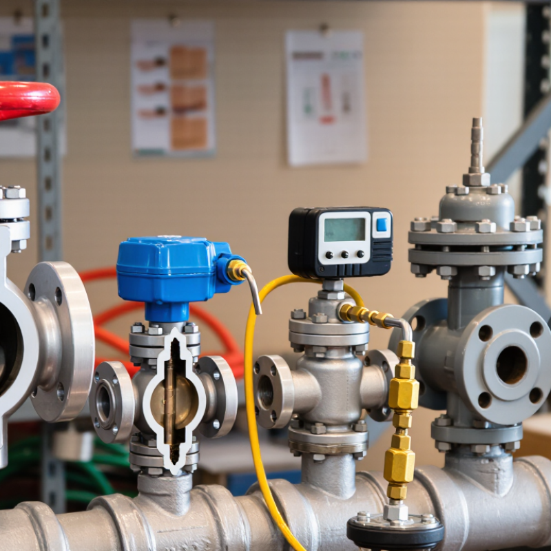
Pressure valves control force by sensing fluid or gas pressure and changing a passage. A pressure-reducing valve lowers downstream pressure: its spring and diaphragm respond as demand changes. A relief valve opens when pressure exceeds a set limit, releasing flow to protect equipment. A back-pressure valve does the opposite kind of job; it opens to maintain pressure upstream. Small differences matter. A gauge beside the valve can reveal pressure swings that a control setting alone may miss.
In a compressed-air system, an undersized valve can cause pressure drops when several tools start together. A valve set too high may waste energy and strain connected equipment. The U.S. Department of Energy’s Improving Compressed Air System Performance guide notes that leaks can waste 20–30% of compressor output. That figure is a useful warning: pressure regulation cannot compensate for a leaking network. Actual performance depends on correct sizing, clean media, and regular checks.
Tips: Match the valve type to the pressure you need to control, then verify its setpoint with a calibrated gauge. Check for hunting, noise, or pressure drift under real operating demand. A neat installation is not proof of a good setting; sometimes the numbers tell a less comfortable story.
What Types of Pressure Valves Are Available?
Pressure relief valves protect vessels, pipelines, and process equipment from excessive pressure. Their operating design determines how quickly they open, how steadily they discharge, and how reliably they reseat. A spring-loaded relief valve uses a calibrated spring to hold the disc against its seat. When system pressure reaches the set point, the disc lifts and releases fluid. This design is simple, fast, and widely used.
Pilot-operated relief valves use system pressure to control the main valve. They can handle high flow rates and maintain tighter pressure control, especially in large systems. However, small pilot passages may become blocked by dirt or sticky process materials. Balanced bellows designs help reduce the effect of back pressure on the set pressure. This feature matters in systems connected to discharge headers or changing outlet conditions. No design is perfect. Selection depends on pressure, temperature, fluid properties, discharge capacity, and maintenance access.
Tips: Check the required set pressure, allowable overpressure, and back pressure before choosing a valve. Confirm that materials suit the process fluid and temperature. During maintenance, inspect the seat, spring, pilot passages, and lifting mechanism. A valve that appears clean may still respond slowly. Testing should follow the equipment manufacturer’s instructions and applicable engineering standards. Small errors in sizing can cause unstable operation, frequent leakage, or delayed pressure relief.
| Valve Type | Primary Operating Design | How It Operates | Typical Applications | Main Advantages | Key Limitations |
|---|---|---|---|---|---|
| Safety Valve | Spring-loaded, pop-action design | Opens rapidly when system pressure reaches the set pressure, producing a characteristic popping action. | Steam boilers, gas systems, and compressible-fluid service | Fast pressure release and straightforward construction | May discharge abruptly and can be sensitive to incorrect sizing or back pressure. |
| Relief Valve | Spring-loaded, modulating design | Opens progressively as pressure rises above the set point and closes as pressure falls. | Liquid piping, pumps, heat exchangers, and hydraulic systems | Provides controlled flow reduction and is well suited to liquid service. | Requires correct sizing to prevent excessive pressure rise during discharge. |
| Safety Relief Valve | Combined pop-action and modulating design | Can provide rapid opening for gas service while also supporting controlled relief behavior for liquid service. | Systems that may handle both gases and liquids | Versatile protection across mixed-fluid applications | Selection must account for fluid phase, capacity, discharge piping, and built-up back pressure. |
| Pilot-Operated Relief Valve | Pilot-controlled piston or diaphragm design | A small pilot valve controls system pressure acting on the main valve, allowing the main valve to open when required. | High-pressure gas pipelines, storage systems, and process equipment | High flow capacity, close pressure control, and reduced spring-size requirements | More complex; pilot components may be affected by contamination, freezing, or blocked sensing lines. |
| Balanced-Bellows Relief Valve | Spring-loaded valve with balancing bellows | The bellows reduces the influence of back pressure on the spring and valve-disc operating forces. | Process equipment connected to headers or closed discharge systems | Improved set-pressure stability under variable back pressure | Bellows integrity must be monitored, and the design generally requires more space and maintenance. |
| Vacuum Relief Valve | Spring-loaded or weighted vacuum-breaker design | Opens inward when internal pressure falls below the allowable vacuum level, admitting air or another compatible gas. | Storage tanks, vessels, and systems subject to draining or condensation | Helps prevent tank collapse and vacuum-related structural damage | Does not protect against excessive positive pressure unless combined with a separate pressure-relief function. |
| Thermal Relief Valve | Small spring-loaded liquid relief design | Relieves pressure caused by thermal expansion of trapped liquid in a blocked-in section of piping. | Liquid-filled pipelines, pump discharge sections, and isolated heat-traced lines | Compact protection for localized overpressure caused by temperature increase | Usually has limited capacity and is not intended to replace a full-capacity relief valve. |
| Rupture Disc | Non-reclosing, scored or membrane-based design | A thin pressure-sensitive membrane bursts at a defined pressure and temperature, creating an immediate opening. | Corrosive, viscous, contaminated, or very fast pressure-rise service | Very fast response, minimal leakage before activation, and no moving parts | Must be replaced after activation and cannot be tested or reset like a conventional relief valve. |
Note: Valve selection should be based on fluid phase, required relieving capacity, set pressure, allowable overpressure, temperature, corrosion conditions, and discharge back pressure.
Pressure-reducing valves keep downstream pressure below a higher, fluctuating supply pressure. They are used in water lines, compressed-air systems, steam services, and other process piping. A direct-acting valve responds to downstream pressure through a spring and diaphragm or piston. It is often compact and straightforward to maintain. For a small workshop air line, for example, it can help deliver a steadier pressure to tools while the compressor cycles.
Pilot-operated valves use a smaller pilot mechanism to control the main valve. They can provide more precise regulation in higher-flow applications, though they may need cleaner fluid and more careful setup. Neither type fixes every pressure problem. Selection depends on flow range, inlet-pressure variation, fluid, temperature, and the downstream pressure required. Check the manufacturer’s published operating limits, and include the expected minimum and maximum flow when sizing. A valve chosen from pipe size alone may perform poorly. That mistake is easy to make.
Installation details matter, too. A pressure gauge downstream helps confirm the actual setting, while a strainer may protect sensitive internals when the service requires one. Leave room for inspection and follow the valve’s specified orientation. Pressure can shift as demand changes. If the outlet pressure creeps upward when flow stops, the valve may be leaking internally or may not suit the application. Diagnose the cause before simply tightening the adjustment; that can hide the real issue.
Sequence, unloading, and counterbalance valves manage pressure in different ways. A sequence valve opens when inlet pressure reaches its setting, allowing a second actuator to operate. For example, a clamp can secure a workpiece before a hydraulic cylinder starts drilling. A built-in check valve may allow reverse flow, but confirm the circuit design before selecting one. Small details matter.
An unloading valve diverts pump flow when system pressure reaches a set level, often reducing wasted energy while an actuator pauses. It is commonly used in accumulator circuits or systems with high-low pump arrangements. A counterbalance valve controls loads that could run ahead of the pump, such as a raised platform lowering under gravity. It maintains back pressure and helps prevent uncontrolled movement. Set pressure depends on the load and circuit layout, so guessing is a poor substitute for measurement.
Tips: Check rated flow, pressure, fluid compatibility, and mounting orientation against the equipment specifications. Adjust settings gradually, using a gauge and a controlled test. Watch for heat, chatter, or drifting loads. Those signs deserve attention. One limitation is that valve behavior can change with temperature and flow; a setup that seems stable during a brief test may still need review under normal operating conditions.
Pressure valves do not all perform the same job. A relief valve opens when pressure rises beyond a set limit, releasing fluid to protect equipment. It may discharge into a return line or a safe collection area. In a hydraulic circuit, this can prevent a pump or hose from facing excessive pressure. The setting must match the system’s rated limits. Small errors matter.
A pressure-reducing valve works differently. It maintains lower pressure downstream, even when inlet pressure changes. This is useful when one machine feeds components that need different operating pressures. For example, a main line might supply a lower-pressure branch for a clamp. Back-pressure valves serve another purpose: they maintain pressure upstream by opening when pressure exceeds a set point. They are often used to stabilize flow in process lines.
Sequence valves control when a second action begins. A cylinder might extend first, then trigger another actuator once the set pressure is reached. These valves can resemble relief valves, so choosing by appearance alone is risky. Check the flow direction, pressure range, fluid, and expected operating conditions. A valve that works well in a clean, steady system may behave differently with pulsating flow or contamination. Real installations are rarely as tidy as the diagram.
How pressure valve types differ
Each bar marks a valve’s primary function. Relief valves protect against excessive pressure; pressure-reducing valves regulate downstream pressure; sequence valves trigger operations at a set pressure; counterbalance valves help control loads; and unloading valves divert pump flow when pressure reaches a set point. Actual designs and applications vary.