How to Choose the Right Flow Control Ball Valve?
Choosing the right Flow Control Ball Valve starts with understanding the system, not simply matching pipe size. The valve must handle the fluid, operating pressure, temperature, and required flow range. A valve that fits physically may still cause unstable control, excessive pressure loss, or premature wear. Small details matter.
Consider the fluid’s properties, including viscosity, solids, and potential for corrosion. These factors influence body and seal materials, as well as how often the valve may need inspection. Check the valve’s flow coefficient, or Cv, against the expected operating conditions. An oversized valve can make accurate adjustment difficult, while an undersized one may restrict flow. Neither issue is obvious from appearance alone.
This guide explains how to compare valve design, materials, connection types, and actuation options for a specific application. It also covers practical checks, such as confirming pressure and temperature ratings from reliable product documentation. Manual and automated valves may suit different systems, and the best choice depends on how precisely flow must be controlled. There is no universal answer. Even a careful selection can require review when real operating data differs from initial estimates. Use the recommendations as a decision framework, then verify critical specifications with the manufacturer or a qualified engineer before installation.
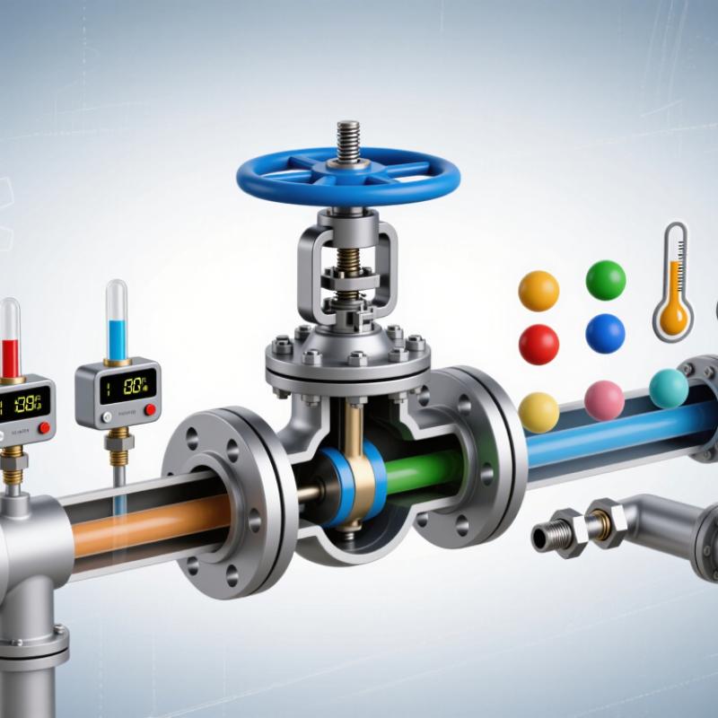
Define the Duty: Flow, Pressure Drop, Temperature, Media, and Shutoff
How to Choose the Right Flow Control Ball Valve?
Define the duty before comparing valve sizes. Record normal, minimum, and peak flow, plus upstream and downstream pressures. The pressure drop across the valve affects its control range and may create noise or cavitation.
Use a documented sizing method, such as IEC 60534-2-1, rather than choosing by pipe diameter alone. A valve that is oversized can make stable low-flow control difficult. Small details matter.
Temperature and media shape material and seal choices. Note the full operating temperature range, not just the usual set point. List the fluid’s composition, viscosity, and any suspended solids; a clean-water assumption can be costly in a slurry line.
The U.S. Department of Energy’s Improving Pumping System Performance sourcebook reports that pumping systems can use 25%–50% of energy in some industrial facilities. That figure applies to whole systems, not a valve alone, but it is a useful reminder to assess pressure losses in context.
Finally, define shutoff expectations: required leakage performance, closing differential pressure, and fail position. I still treat the stated duty as a draft until operators confirm real startup and upset conditions.
Choose Full-Bore or Reduced-Bore Ports for Capacity and Pressure Loss
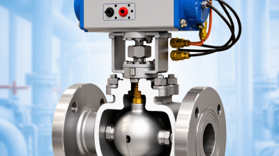
For a flow-control ball valve, port size affects capacity and pressure loss. A full-bore valve has an opening close to the pipe’s inside diameter, so it usually creates less restriction. This helps where high capacity matters, such as a water line feeding several process branches. Less loss. The trade-off is a potentially larger, heavier valve.
A reduced-bore valve narrows the flow path. At the same flow rate, fluid speeds up through the smaller opening, and pressure loss generally increases. This may suit a line with modest capacity needs or tight installation space. Don’t select by pipe size alone: compare the valve’s flow coefficient, Cv or Kv, with required flow, fluid properties, and available pressure differential. A tidy first estimate can still miss peak demand.
Check the demanding operating case, not only normal conditions. For example, record upstream and downstream pressures while the pump runs near its expected maximum. Then verify velocity, noise, and cavitation risk with a qualified engineer. If the valve will regulate continuously, check its control range and typical operating position too. A bigger port is not automatically better. Sometimes the sizing choice needs another pass.
Size with Cv: 1 US gpm of Water at 1 psi Pressure Drop Equals Cv 1
A flow control ball valve should be sized around its required flow and pressure drop, not pipe diameter alone. Cv is the capacity reference: one US gallon per minute of water flowing through a valve at a 1 psi pressure drop equals Cv 1. This definition is used in ANSI/ISA-75.01.01, the control-valve sizing standard aligned with IEC 60534-2-1.
For water, a useful estimate is Q = Cv × √ΔP, where Q is US gpm and ΔP is psi. At 4 psi pressure drop, a valve with Cv 5 passes about 10 gpm. Start with the math.
Then check the valve’s flow curve at the intended opening. A ball valve’s Cv changes as the ball turns, so a valve that matches the maximum flow may offer poor control at normal flow. The ISA/IEC sizing method and Crane Technical Paper 410 both underline why fluid properties and pressure conditions matter in flow calculations.
For liquids other than water, account for specific gravity; also review minimum and maximum flow, upstream pressure, and downstream pressure. This is where sizing gets less tidy. A calculated Cv is a starting point, not proof that the valve will control smoothly in the installed system. Compare the required operating range with the valve’s published Cv-versus-opening data before selecting its size.
Verify ASME B16.34 Pressure–Temperature Ratings for the Valve Body
A flow control ball valve must withstand the highest pressure and temperature expected at its body, not just the normal operating point. ASME B16.34-2020 provides pressure–temperature ratings by valve class and material group. For Group 1.1 carbon steel, its rating table lists 285 psi for Class 150 at 100°F, falling to 200 psi at 400°F. Check the curve. These figures are not universal: material grade, class, and the applicable standard edition matter. Confirm the exact body material and rating table before comparing valve options.
Use the maximum credible operating temperature with the corresponding pressure rating, then include foreseeable surges and process conditions in the engineering review. A valve rated for 285 psi at ambient temperature may not be suitable at the same pressure in a hot line. That detail is easy to miss. Also, do not treat a hydrostatic test pressure as the valve’s continuous service rating; test requirements and operating limits serve different purposes. I would document the selected material group, class, design temperature, and allowable pressure on the datasheet. One imperfect habit in many reviews is checking nominal size first and body rating later. Reverse that emphasis when service conditions are demanding, and verify the current ASME B16.34 edition with the project’s applicable specifications.
Specify Shutoff Using ANSI/FCI 70-2 Leakage Classes, Including Class VI
Choosing a flow control ball valve starts with defining how much leakage the process can tolerate.
ANSI/FCI 70-2 classifies control-valve seat leakage from Class I through Class VI. Class VI is often specified when very low leakage is needed, but it does not mean zero leakage. Its allowable rate is based on the valve’s nominal port size and the standard’s test procedure.
Specify the leakage class alongside the test medium, pressure differential, and operating conditions. A soft seat may help achieve Class VI, yet temperature, fluid compatibility, and repeated cycling can affect sealing performance. On a test bench, the acceptance check should follow the stated procedure; a visual “no drip” check is not a substitute.
One detail is easy to miss. Class VI leakage limits are expressed as a defined rate, not an absolute promise of tight shutoff in every installation. If even minor leakage could create a process hazard or disrupt production, discuss the actual service conditions with the valve supplier and consider how the valve will be tested and maintained. It may feel overly cautious, but the specification should describe the required performance—not just name a class.